
Dynamass T12i Technology is deployed to actively detect and alert users to wheel impacts, skew bogies, excessive lateral forces and incorrect vehicle loading. In addition, the Wheel Impact Detector functions as a full in-motion weighbridge, providing all related data. The system is designed for operation at main line speeds, up to 120 km/hr.
Wheel impacts and excessive lateral forces are detrimental to rail network as they:
- Damage or reduce the life of the track structure
- Damage or reduce the life of wagon components
- Can ultimately lead to component failure or derailment
Product Features and Highlights
Wheel Imperfection and Skew Bogie Detector
The WID detects and raises alerts for the following conditions. All have multiple alarm levels, all of which are configurable.
- Wheel impact force
- Wheel lateral force
- Gauge spreading force
- Skew bogie
In-Motion Weighbridge
The T12i system also functions are a traditional in-motion weighbridge, providing the same information. In addition, the weighbridge functionality is leveraged to monitor and raise alerts for the the following conditions:
- Skew loading, end-to-end
- Skew loading, side-to-side
- Vehicle overload
- Vehicle under-load
- Axle overload
The T12i Sensors
The system makes use of a combination of vertical load receptors, lateral receptors and accelerometers. These sensors collectively provide coverage for approximately 5 metres of linear track, which becomes the continuous detection zone. This instrumented length ensures 100% coverage of the wheel circumference, with no dead zones. Over this length, all measurements are made, including wheel impacts, skew bogie detection, as well as lateral force and weighing measurements.
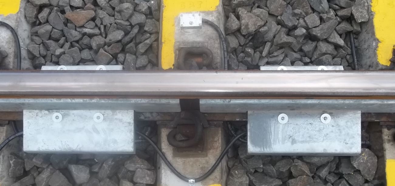
Retrofit Technology
All sensors are retrofitted to the existing track section, creating a system from the existing track. Work can therefore be carried out safely between train movements without taking the rail out of commission or disrupting operations.
There is thus no requirement for:
- Sleeper substitution or modification
- Rail cutting or replacement
- Concrete plinth and/or supports
- Ballast modification
Finally, the retrofit technology also makes complete system relocation a cost-effective option. Relocation cost is typically 15%-20% of the cost of a new system.
Microprocessor-Based Technology
Based entirely on microprocessors, the T12i system is energy-efficient and reliable, while providing excellent performance. All components are industrial and solid-state, with no moving or rotating parts. Dedicated firmware removes the need for an Operating System, increasing stability while reducing costs and maintenance requirements. The result is a simpler, more reliable system, which is ideal for harsh operating environments.
The hardware is compact, resulting in a much smaller footprint than traditional systems. All Dynamass T-series products are housed in a small, vandal-proof 500×400 mm trackside enclosure, which is easily installed by a small team. This makes the traditional trackside building or equipment container redundant.
The efficiency of the system coupled to power-optimised firmware translates into a system that is ideal for solar-powering. A 200W solar system can run a full Dynamass-T12i with an AVI reader. The solar powering makes the system an attractive option for remote, unsupervised locations.
Automatic Vehicle Identification (AVI)
The Dynamass-T12i system is compatible with the widely-used Amtek / Transcore AVI system (AAR & ATA), as well as the more modern Gen-II standard. The benefit of the AVI system is that each wagon has a unique truck number/vehicle class attached to it in addition to the measurement information. This is very important to ensure that measurements are assigned to the correct vehicles when undesirable conditions are detected. The reader is a simple optional upgrade to the base system and is mounted to the track enclosure as shown below.

Reporting
Alarm Content
For each parameter that is out of range, an alarm is generated. The alarm contains the following fields.
- Site identifier
- Date and time of event
- Direction of travel
- Vehicle position in train
- Vehicle number and vehicle class
- Vehicle speed
- Alarm type (impact, lateral, overload, etc.)
- Alarm severity: levels 1 to 3, with increasing severity
- Alarm component: axle, F/R bogie, individual wheels
- Alarm value: magnitude of alarm, in calibrated units
- Vehicle type (wagon or locomotive)
Train Measurement Data
For each train measurement, the following fields are produced.
- Site identifier
- Date and time of measurement
- Direction of travel
- Vehicle speed
- Vehicle type (wagon or locomotive)
- Vehicle axle count
- Vehicle number, class and owner
- Max. wheel vertical force (impact), for each wheel
- Max. wheel lateral force (left and right), for each wheel
- Gauge Spreading Force
- Vehicle mass
- Vehicle mass distribution – front and rear
- Vehicle mass distribution – left and right
Installation Requirements
- Installation requires approximately 20 hours.
- Straight, level section of track required, where speeds exceed 15 km/hr.
- Power required (220V AC / 24V DC / 12V DC).
- No cutting of the track.
- No sleeper modification.